A thorough understanding of WSR-88D Doppler radar sampling issues is crucial for proper identification and assessment of severe thunderstorm signatures. Sampling issues include radar horizon, scan strategy, beam width versus range, aspect ratio, and range folding. While the WSR-88D is a very powerful and sensitive radar, changes in storm appearance can still occur as storms approach or move away from the radar due to these problems. Thus, unless radar sampling issues are understood, improper signature interpretation could occur. However, once understood and accounted for in displayed radar data, proper analysis is likely.
RADAR HORIZON: The radar horizon presents a problem for viewing storms as they increase in range from the radar data acquisition (RDA; i.e., antenna). The radar beam (under standard refraction) increases in height with range due to the earth's curvature (assuming similar terrain). Thus, for finite depth phenomena, such as mesocyclones, gust fronts, low-level rotational circulations, and low-topped convection, the chances of the radar beam overshooting the phenomena increase with increasing range (Fig. 1). Also, the same storm viewed by several radars will produce different storm appearances, especially if the same elevation angles from each radar are used (Fig. 2).
 |
Fig. 1: Idealized example of the radar horizon problem. The bold line is the exaggerated curvature of the earth. The curly line represents a thunderstorm. Depending on the distance of the storm from the radar, the radar beam (the 2 adjacent straight lines) will sample different parts of the storm. |
 |
Fig. 2: Example of three different radar sites (KFDA, KDYX, and KTLX) sampling an idealized thunderstorm near the northern Texas/Oklahoma border. The same radar elevation angles from the three radars will sense different parts of the storm, due to their varying distance from the storm. |
Examples of possible effects radar horizon could have on storm analysis are given below.
Example 1: A distant storm may contain a mesocyclone in the low- and middle-levels. However, the 0.5 degree elevation angle may only be able to discern a broad, weak circulation near the top of the circulation, when in fact a stronger, tighter circulation may be present below the radar beam.
Example 2: A severe storm is moving away from the radar. On successive radar volume scans, the storm's mesocyclone appears to be weakening as the cell moves away. This could be interpreted as a weakening storm, with no more warnings needed. While this could be the correct assessment, it also may not be. The storm may be just as strong, but since the beam is looking progressively higher in the storm where the cyclonic circulation may be weaker, it gives the impression of a decaying circulation. The opposite could be true for a storm approaching the radar.
Example 3: Low-level reflectivity structure identifies a severe storm (perhaps a supercell with a hook echo or a bowing line segment with a leading edge inflow notch identifying a possible tornado location). However, as the cell moves far enough away from the radar, some earlier severe reflectivity signatures no longer appear, or appear to a lesser, more subtle degree than before. Here, a given radar elevation angle is progressively looking higher in the storm, thus overshooting earlier detected lower-level features, which may still be present.
Example 4: An outflow boundary may be present relatively close to the radar, which may be a critical factor if intersecting other storms. However, if the boundary moves away from the radar, it may appear to dissipate or disappear, despite its continued presence, if the radar beam overshoots it.
In an attempt to overcome radar horizon problems, it is very important to dial into an adjacent radar that is closer to the storms to obtain the maximum resolution and view the lowest level possible within the storms. Otherwise, for distant convection, assume that mesocyclones are at least as strong below the radar beam as that shown on the 0.5 degree slice (elevation angle).
SCAN STRATEGY/VOLUME COVERAGE PATTERN: The radar's scan strategy affects the sampling of precipitation elements. The radar's Volume Coverage Pattern (VCP) determines its scan strategy. There are a number of available VCPs for different purposes. VCP 12 (14 elevation angles scanned in 4.5 minutes) is ideal for convection, allowing rapid vertical assessment of thunderstorms. VCP 212 is similar to VCP 12 but helps reduce range-obscured velocity data. VCP's 12 and 212 are usually the most used scan strategies during active convective weather situations, allowing for accurate, quick data availability to NWS meteorologists. VCP 21 (9 angles in 6 minutes) is best during non-convective (i.e., stratiform) precipitation events such as general rain or snow. VCP 21 allows for excellent radar returns without the need to scan high up into thunderstorms. VCP 121 is similar to VCP 21 but helps reduce range-obscured velocity data. VCPs 31 and 32 allow scanning of 5 elevation angles in 10 minutes, and are designed for periods with no precipitation (i.e., "clear air mode"). In these VCPs, the radar is particularly sensitive and can pick up on very weak non-precipitation returns. Radar operators can switch VCPs as needed before, during, and after precipitation events.
BEAM WIDTH VERSUS RANGE: A fundamental concept of radar is that the radar beam becomes wider with range. The beam width for the WSR-88D is 0.96 resulting in a beam diameter of about 2 nmi at 124 nmi from the radar (not that much). The definition of the edge of a radar beam is where the power lowers to one-half (the "half-power point") that of the beam centerline . Some information, especially for velocity estimates, may be returned from side lobes outside the defined radar beam. Since the beam increases in width with increasing distance, velocity estimates likely will experience more averaging with range, since varying wind speeds within a sample volume (radar beam) are being used to calculate the radar displayed pixel value. In addition, reflectivity data will appear more "blocky" due to a wider beam, thereby decreasing the retrieved resolution of important reflectivity signatures at far out ranges. In addition, dBZ values may be averaged to slightly less than reality.
ASPECT RATIO: Aspect ratio deals with the beam width versus range problem. Aspect ratio is the ratio of the actual physical size of a particular precipitation or flow field entity (tornado, mesocyclone, hook echo, etc.) to the size of the radar beam. If the phenomena is very small compared to the sample volume, then the phenomena could essentially be invisible to or more likely not well sampled by the radar. Conversely, a large feature compared to a smaller beam (closer to the radar) would result in a more accurate presentation of the feature. To illustrate aspect ratio, consider Fig. 3. Shown are 3 idealized identical sized mesocyclones at varying distances from the RDA. Retrieved velocities from the most distant circulation would be averaged to near zero, although the radar likely would resolve some sense of circulation depending on exactly how the beam intercepted the rotation. On the other hand, the meso closest to the radar would be resolved well with the beam shown returning near zero velocities (i.e., zero line) and the 2 adjacent beams (not shown) retrieving maximum inbound and outbound velocities. This example is exaggerated.
 |
Fig. 3: Idealized/exaggerated example of how 3 same size mesocyclones might be sampled by a radar beam depending on the distance of the entity from the radar site (black dot). |
Even at distant ranges, circulations usually are large enough and the beam small enough to allow for at least some degree of resolution. However, in general, for distant reflectivity and velocity features, measured data will be averaged to lower values than reality. Conversely, the radar will display values for features near the radar that are closer to reality as a narrower beam allows for more beam "cuts" (samples) through the feature, and thus less averaging. For example, a relatively large diameter mesocyclone at close ranges would be sampled by several beams, resulting in maximum inbound and outbound winds defining the edges of the meso core, and a near zero line in-between where winds within the circulation are normal to the beam. For distant circulations, a mesocyclone may appear as gate-to-gate shear (with symmetric or asymmetric inbound and outbound velocity values) due to a wider beam, when in reality the circulation may not be that "tight." This aspect ratio problem is illustrated in Fig. 4.
 |
Fig. 4a: Idealized example of two adjacent radar beams from the RDA (radar site) sampling a mesocyclone (bold circle; top figure). Here, the beam center line (dashed line; maximum beam power axis) intersects the edges of the meso's solid body rotation core where maximum inbound and outbound velocities are found. The resulting WSR-88D display (bottom figure at left) would show symmetric "gate-to-gate" shear in two adjacent pixels (radar beams), one with inbound (minus sign) and one with outbound (plus sign) velocities. Due to a wider beam width at long distances from the radar, displayed radar velocities would be averaged a little lower than actual mesocyclone velocities. |
 |
Fig. 4b: Same as Fig. 4a except a different radar sampling of the mesocyclone (assume the same size and same intensity as in Fig. 4a) is shown. Here, the solid body rotation edges are sampled within the same beam. In the corresponding radar display (bottom figure at left), a near zero velocity is shown for Beam 2 (within which the meso is sampled), since both inbound and outbound meso velocities within the beam cause a net near zero effect. The adjacent two pixels show symmetric inbound and outbound velocities which are averaged lower than those shown in Fig. 4a since Beams 1 and 3 are not sensing the core of the meso. Thus, despite the exact same meso in Figs. 4a and 4b, potentially different sampling in consecutive volume scans could give false radar-indicated meso trends. Beware of scan-to-scan radar trends, especially for distant small circulations. |
 |
Fig. 4c: In this example, the mesocyclone is one-half beam width larger than in Figs. 4a and 4b. Here, Beam 1 intersects the meso optimally along the beam's center line. Therefore, the radar displays a maximum inbound velocity in the topmost pixel. Beam 2 contains outbound and also zero (where the meso core is perpendicular to the beam) velocities. Thus, the pixel for this beam would show a net weak outbound. Beam 3 contains weak outbound velocities as well, as the meso core is between Beams 2 and 3 where beam power is lower than the center line. The result is an asymmetric display, with 2 weaker outbound and 1 stronger inbound velocity. Again, averaging in the beam causes displayed velocities to be less than actual meso values, especially for the outbounds shown here. |
Due to the aspect ratio, rotational circulations associated with storms moving progressively farther from the radar may appear to weaken and change appearance, despite their continued strength. Conversely, mesocyclones associated with approaching storms will be sampled better due to a narrower beam width. Reflectivity structure may lose some identity for far away storms.
Thus, aspect ratio and radar horizon problems both can cause false radar-indicated changes with varying distance from the radar. However, since the WSR-88D radar beam is only 2 nmi in diameter at 124 nmi range, this is not a major concern until convection propagates very far from the radar. Velocities will be averaged with increasing distance, with potential changes in appearance from volume scan to volume scan. Important reflectivity signatures may become a little more subtle or blocky at distant range. Thus, never assume storms are weakening as they move far away from the radar. Dial into an adjacent radar to complement the primary radar, if necessary. Also, use reflectivity patterns to help assess whether temporal changes in velocity measurements are due to actual storm changes, radar sampling problems, or a combination of the two.
RANGE FOLDING: This is a problem than could adversely affect interpretation of features in velocity and spectrum width data. Areas of range folded data (purple haze) can occur in any location where reflectivity is being returned from a variety of ranges along the same radial. This is of particular concern beyond the maximum unambiguous range (Rmax) for the given pulse repetition frequency (PRF). However, strong storms should still return enough power to generate useful data within the range folded area. By changing the PRF, the Rmax also will change, allowing possible visualization of an important feature. Decreasing the PRF will increase Rmax. Look at other elevation angles using the primary radar and dial into other radars if possible to alleviate any range folded problem. Fortunately, new Volume Coverage Patterns (VCPs) have been developed with can mitigate the effects of range folding.


 Weather Story
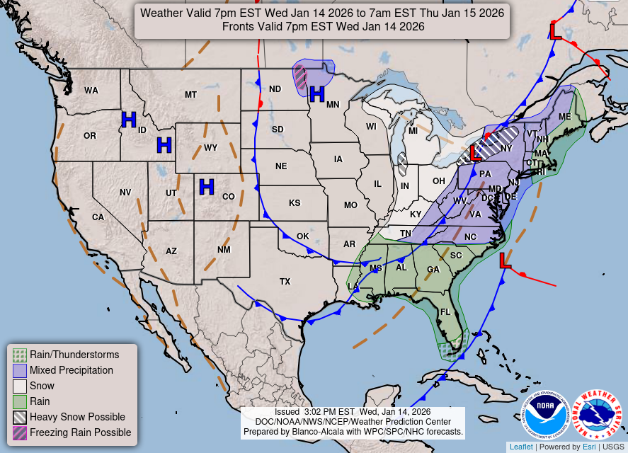 Weather Map
 Local Radar